
shining bright

a British lighting manufacturer with a difference

Obsessed with solving problems, not just selling 'stuff': we were born from a belief that the lighting industry deserved better.

What Is an FPGA Chip and How Does It Work?

An Fpga Chip is a reconfigurable semiconductor device that can be programmed for specific digital tasks. Unlike a fixed-function processor, it allows engineers to reshape internal hardware after manufacturing. This flexibility makes FPGAs useful in telecommunications, industrial control, medical equipment, automotive systems, and scientific instruments.

Inside an Fpga Chip, configurable logic blocks perform Boolean operations and store temporary results. Programmable routing channels connect these blocks across the silicon. Engineers describe the desired circuit with hardware languages such as VHDL or Verilog. A synthesis tool converts that description into a configuration file. The file then programs lookup tables, flip-flops, memory blocks, and input-output resources. Tiny switches change the signal paths.

That process supports parallel execution. Several operations can run during one clock cycle, often reducing latency in demanding applications. A processor usually follows instructions in sequence. An FPGA can build a pipeline that moves data through multiple stages, like parts moving along a factory line. However, flexibility does not guarantee better performance. Development can require specialized knowledge, careful timing analysis, and repeated hardware testing.

Real projects also expose practical limitations. An FPGA may consume more power than a custom chip for the same task. It can cost more than a microcontroller in simple designs. The comparison is not always clean. Device families differ greatly in speed, memory, power use, and software support. Understanding how an Fpga Chip works therefore requires more than memorizing its architecture. It requires examining the design goal, workload, operating environment, and evidence from actual measurements.
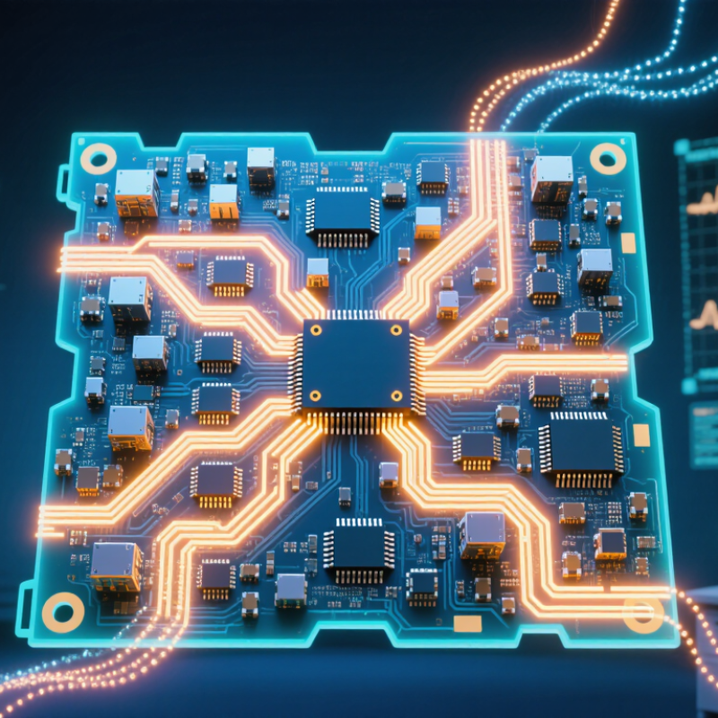
What Is an FPGA Chip and How Does It Work?

FPGA Chip Definition and Core Characteristics

What Is an FPGA Chip and How Does It Work?

FPGA Chip Definition and Core Characteristics

An FPGA, or field-programmable gate array, is a semiconductor device configured after manufacturing. Unlike a fixed circuit, it can be rewired for a specific task. Its internal structure usually includes configurable logic blocks, routing channels, memory elements, and input/output circuits. Small lookup tables perform logic operations, while flip-flops store values on clock edges. These parts work together through programmable connections.

Engineers describe the design with hardware languages, then convert it into a configuration file called a bitstream. The bitstream sets logic functions and routing paths inside the chip. For example, an FPGA can receive sensor samples, process several values in parallel, and send results within predictable clock cycles. This parallel structure often reduces latency. It also supports hardware updates without redesigning the physical circuit.

Flexibility is a core characteristic, but it is not unlimited. Available logic cells, memory, pins, and routing resources constrain the design. Timing closure can become difficult when signals travel across a crowded layout. Power use may also increase when many circuits switch simultaneously. I once treated reconfigurability as an automatic advantage, but that view was incomplete. A poorly planned design can waste resources and perform worse than a simpler circuit. Careful clock planning, simulation, and hardware testing remain essential. Real measurements matter.

FPGA Architecture: Logic Blocks, Routing, and Input/Output

What Is an FPGA Chip and How Does It Work?

An FPGA is a reconfigurable chip built from three main systems: logic blocks, routing resources, and input/output circuits. Unlike a fixed-purpose chip, it can be programmed to perform different digital tasks after manufacturing. In practical testing, the architecture feels like a large electronic workshop. Each logic block handles a small operation, while the routing network connects those operations into a working design.

Logic blocks usually contain lookup tables, registers, and control elements. A lookup table can produce a chosen output from several input patterns. Registers store values between clock cycles, which helps create counters, pipelines, and state machines. My first mental model treated these blocks as independent calculators. That was incomplete. Their real strength comes from coordinated timing and carefully planned connections.

Routing resources act like programmable wiring across the chip. They carry signals between logic blocks, memory areas, and I/O pins. Good routing reduces delay and prevents congestion. Poor routing can make a correct design run slowly.

Input/output circuits connect internal logic with sensors, displays, memory devices, or other electrical systems. They also manage voltage levels, signal timing, and data direction. Small timing errors matter. A design may simulate correctly yet fail on a physical board because signals arrive too late. Careful testing, timing analysis, and measured hardware observations make FPGA results more reliable.

How FPGA Configuration and Reprogramming Work

An FPGA is configured by loading a digital design file called a bitstream. This file sets the behavior of logic blocks, signal routes, memory elements, and input-output circuits. Unlike fixed hardware, an FPGA can change after manufacturing. That flexibility is its main practical advantage.

During configuration, a controller transfers the bitstream into configuration memory. Many devices use volatile memory, so they need a fresh configuration after power is removed. Nonvolatile storage can reload it automatically during startup. The process also checks timing, data integrity, and configuration status. A single corrupted bit may create an intermittent fault, which is difficult to diagnose. Careful verification matters.

Reprogramming usually happens through a debugging port, a processor, or an external memory device. Engineers revise hardware description language code, synthesize it, place and route the design, then generate a new bitstream. The FPGA may be fully reconfigured or updated in selected regions while other logic continues running. Partial updates save time, but they demand strict isolation between changing and active circuits. In laboratory testing, a design can work perfectly at room temperature and still fail under voltage variation. That result is a useful warning: simulation is evidence, not proof. Configuration files should be versioned, protected from accidental changes, and tested on the actual board. The workflow is powerful, but not effortless.

The Step-by-Step Process of Running Designs on an FPGA

An FPGA is a programmable chip built from configurable logic blocks, memory, and routing channels. Unlike a fixed-function processor, it can become a custom digital circuit. The design begins with a hardware description, schematic, or graphical logic model. Engineers define functions such as counters, filters, or communication interfaces.

A typical workflow starts with writing and checking the design. Simulation helps reveal incorrect logic before hardware testing. The development tool then synthesizes the description into basic logic elements. Next, it maps those elements onto available resources inside the FPGA. Placement assigns physical locations, while routing connects them with internal wires. Timing analysis checks whether signals arrive quickly enough. The tool generates a configuration file, often called a bitstream. This file is loaded into the FPGA through a programming interface. After configuration, input pins, clocks, and internal signals begin driving the circuit. The FPGA executes these operations in parallel, not as a simple instruction list. A design may pass simulation but fail on the board because of timing, noise, or an overlooked reset condition. That gap requires careful measurement and revision.

Tips: Keep clock planning simple. Add reset logic early. Check timing reports, not only functional results. Use visible test signals when debugging. The first build is rarely perfect. Leave room for correction.

Common FPGA Applications and Key Advantages

An FPGA is a reconfigurable chip built from programmable logic blocks, routing channels, and memory elements. Engineers describe its hardware behavior with specialized design languages. The device then configures itself after power-up. Unlike a fixed processor, it can run many operations in parallel. That difference matters.

Common FPGA applications include industrial machine vision, wireless infrastructure, medical imaging, robotics, and high-speed financial data processing. In a factory, an FPGA can inspect several camera feeds while controlling motors with predictable timing. In edge systems, it can filter sensor data locally, reducing network traffic and response delays. A 2024 FPGA market forecast estimates global revenue will grow from 9.8 billion dollars in 2024 to 19.3 billion dollars in 2029, representing a 14.5% compound annual growth rate. The forecast is useful, but not guaranteed.

Key advantages include low-latency processing, flexible hardware updates, strong parallel performance, and long product support cycles. FPGAs can also reduce system changes when requirements evolve. Yet flexibility has a cost. Development often requires hardware expertise, careful timing analysis, and longer verification. Power efficiency may decline when designs use excessive logic or memory. In practice, the best result depends on disciplined architecture, not simply choosing a programmable chip. That point is easy to miss.

What Is an FPGA Chip and How Does It Work?

Representative timing diagram showing how programmable logic can process digital inputs through configurable logic and routing. In this example, output Y follows the logic expression A AND B.

How to read the chart: The clock provides synchronization, inputs A and B carry binary signals, and output Y changes according to the configured logic function. Unlike software running sequentially on a processor, FPGA logic blocks can operate in parallel and respond within defined clock cycles.

Our story

When The Light Went On

The idea for Acrospire was formed in 2012 when founder Tim envisioned a different kind of lighting manufacturer: one that would not only deliver outstanding customer experiences but also prioritise fair treatment for its employees.

We’ve come a long way

Working from any nook and cranny we could find

Motivated by the belief the industry wanted and needed better, Tim shared his plan to establish his own venture with Hatty, who simply couldn't let him do it alone.

The rest, as they say, is history.

Protecting local jobs and ensuring the best quality possible.

The products sold should, where possible be manufactured here in the UK

Working from a rented office by day and assembling lanterns in a garage at night, Tim and Hatty set to work.

11 Years later

and a lot has changed

Acrospire now inhabits a 14000² ft manufacturing facility in Basingstoke, Hampshire. We’re a proud partner of the Made in Britain scheme, ISO9001 certified and a member of all relevant lighting industry trade bodies.

We've built a reputation to be proud of

Along with great relationships with our customers and a great team! We've attracted some of the most experienced members of the lighting industry, all by following one golden rule.

A simple ethos

Creating work to be proud of

That runs through all that we do. Customers who have made the switch to Acrospire have found working with us to be a breath of fresh air.

Market leading warranty

If you’re a professional in the lighting industry, you’re probably familiar with warranties that range from 3 to 10 years, with extensions available on special request or at additional cost. At Acrospire, where we’re proud to be different, we offer a market-leading simple 12-year warranty, as standard.

Tight Control on Quality

We focus on our customers not our competition. We manufacture our products in the UK: with the exception of our solar products, our supply chain is within a 60-mile radius of our factory in Basingstoke: to maintain greater control over quality. We al

Speed is key

Speed of response is crucial when it comes to resolving warranty issues. If we’ve made a mistake, we own it, get to the root cause, and fix it as quickly as possible. We believe in timely communication with our customers and making the resolution pro

Test and Test Again

We believe in independent testing and certification. Our new product development is in line with ISO 9001. Many of our products hold ENEC Certification. To meet the requirements of ENEC we also send random product samples for third party safety testi

Quality by design

Our product design is another key factor in our ability to offer a 12-year warranty. We value engineer rather than cost cut, never compromising on quality. We stick to our processes and engage with our supply chain to ensure that every product meets